Abstract: This paper describes in detail the block diagram and working principle of the electric actuator and explains its application in a thermal power station. It analyses fault factors and remedies in different service periods and sets out the key maintenance work, providing practical guidance for daily operation.
Keywords: actuator; fault analysis; performance; maintenance
Henan Shenma Nylon Chemical Co. is one of China's major production bases for nylon 66 salt. Its thermal power station uses nine electric actuators made by Tianjin No.7 Automation Instrument Factory, models A+RS100 and B+RS160. They adjust the primary/secondary fan and induced-draught fan dampers of three boilers, controlling bed temperature, flue-gas oxygen content and furnace negative pressure — one of the key conditions for stable operation of the circulating fluidised-bed boilers.
The thermal power installation uses split-type modulating actuators consisting of two parts: a remote-controlled actuator installed in the field and a positioner installed in the control room. The block diagram is shown in Fig. 1.
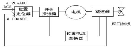
Fig. 1 Block diagram
The positioner compares and amplifies the control signal against the field position feedback and outputs to the actuator; the actuator drives the single-phase motor accordingly, and the valve position follows the gear reducer. When the difference between feedback and control signal falls below the positioner dead band, the motor stops — one stroke complete.
These actuators have run for many years at the plant. Because of their important control duty, they repeatedly disturbed long-period stable operation in the early days, so understanding the working principle, recognising fault symptoms and mastering routine maintenance are essential. The schematic is shown in Fig. 2.
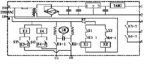
Fig. 2 Operation schematic (S1/S2: travel limit microswitches; S3/S4: torque limit microswitches; RT: thermal protection switch)
When power is applied, contactors K1 and K2 energise and contacts K1-1/K2-1 close. When the control signal exceeds the feedback signal, the positioner connects terminal 20 to 15: the motor runs in the opening direction, driving the reducer and the cam (feedback rises). On overtravel S1 opens, K1 drops out and the motor stops. If overload occurs during travel, S3 closes, relay K3 picks up and locks itself in via K3-2 while its normally-closed contact K3-1 drops K1 and stops the motor. When the control signal is smaller than the feedback, the positioner connects 20 to 16 and the motor runs in the reverse direction, with the same sequence.
Finally, via the cam the reducer turns a single-deck conductive-plastic potentiometer, and current transducer TAM2 outputs a 4–20 mA DC feedback signal for remote indication.
Whether an actuator runs reliably and performs its required function within the specified time and conditions depends on its performance indices, usually expressed as the mean time between failures (MTBF). Important parameters — intrinsic error, hysteresis, damping, dead band — reflect actuator quality to a considerable degree.
Technical data of this actuator: one input channel, 250 Ω; intrinsic error 1%; hysteresis 1.5%; dead band adjustable 0.5%–3%; no disturbance in damping characteristics.
3.3.1 Early period (run-in)
Faults in the run-in period are complex and multi-causal: selection errors, design/manufacturing problems, installation and environment. For example, too small a torque selection affects modulating speed or prevents modulation entirely. Actual cases: valve stem not rigidly fixed to the actuator and coming loose; power and signal cables in one conduit causing interference; nearby unscreened large motors disturbing stable operation; positioner fuse rated too high, damaging its internal choke. Watch for these, find and fix them promptly to avoid unnecessary losses.
3.3.2 Mid period (adaptation)
In mid-service the overall performance stabilises. Problems mostly stem from individual components with quality defects — position current transducer TAM2, contactors K1/K2, torque microswitches. Besides reporting to the manufacturer, keep statistics and stock spares for replacement.
3.3.3 Late period (wear-out)
In late service, component ageing and mechanical wear dominate: motor windings age, insulation drops and operation becomes unstable; poor lubrication reduces stability; ageing comparator coils or position transducers degrade positioning accuracy; worn reducer parts make modulation impossible. Inspect periodically to prevent major failures, and keep a spare unit.
Objective factors also account for a share of faults — trampling by personnel, jammed dampers, process mis-operation, etc.
From the practical experience of field maintenance staff, actuator maintenance should focus differently at each service stage. We usually do the following:
The motor and drive parts need lubricating oil, whose viscosity changes with temperature. Too low: gear wear increases; too high: sluggish operation. Regular lubrication extends service life.
Reliability first requires a suitable environment — avoid damp conditions that cause short circuits and other faults.
Routine inspections catch hidden dangers in the bud and at least help fault-finding, avoiding detours.
Record every fault handled: symptoms, analysis and search process, root cause, remedy, prevention. This provides reference for similar problems and, through fault curves, raises fault-finding skill — twice the result with half the effort.
Timely technical training helps thermal-power operators lose their nervousness, raises skill levels and ensures everyone can handle common faults.
Years of actual maintenance show satisfactory actuator performance. From the maintenance point of view, we hope designers of such electromechanical systems will fully consider ease of field maintenance and management: simplify and modularise to cut failure rates and ease fault isolation; add intelligence to allow online commissioning; standardise components for easy repair; and introduce appropriate fault-tolerance/error-correction. Actuator maintenance will then become ever easier and the actuators ever more widely used in industry.