随着汽轮机组容量的不断增大,火力发电厂的热力系统越来越复杂,自动化水平也越来越高。为了保证电厂的安全经济运行,必须提高控制系统的灵活性与可靠性。为此,对其调节控制系统中配套的执行机构提出了大力矩、长行程、高精确度、多功能、快速切断及快速调节等高难度的技术要求。但目前控制系统中采用的各种阀门执行器存在着卡涩、滞后、速度慢等缺陷,严重影响了机组的安全经济运行。随着机电液一体化技术的发展,国外已开发出智能成套式电液执行器:该执行器没有外置附属设备,系统简单,运行可靠,操作方便,近几年成为美国一些电厂的首选执行机构。
智能型阀门电液执行器是由液动、控制、机电和计算机技术综合为一体的特殊智能型电液执行器,由两大部分组成:机电伺服控制系统和液压驱动系统。
机电伺服控制系统的原理框图如图 1 所示,该系统采用数字化闭环控制方式。其基本思想是:位置给定指令和位置反馈信号共同对步进电机进行控制,使其成为一个较理想的数字式积分环节;在此基础上引入直接检测运动部件的测量环节,构成包含各种误差源和非线性环节的全闭环系统,并通过计算机控制器对系统的运行进行最少拍控制。这样,该系统不但可使运动部件的定位精度由检测环节的测量精度决定,而且可对各种干扰和非线性因素对运动部件产生的影响进行有效的动态校正,使任何时刻运动部件的实际位移量总是严格跟随指令值变化,从而保证运动部件的位移具有较高的动态精度。
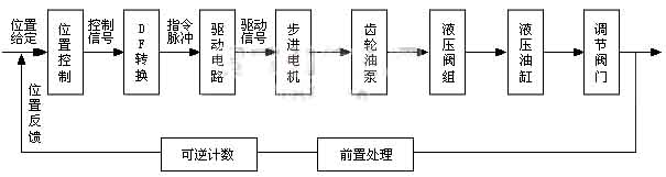
图 1 机电伺服控制系统原理框图
液压驱动系统由双杆液压油缸、液压阀组、双向内啮合齿轮油泵、高压电磁阀及弹簧等组成液压驱动回路,系统回路的原理框图如图 2 所示。该回路采用双向定量内啮合式齿轮油泵,通过改变油泵输入转速和油流的方向,控制液压缸的运动方向和速度。回路中压力的大小取决于负载的大小,因而没有过剩的压力和多余的流量,效率较高。回油背压可直接作用在油泵的吸入口上,变为推动油泵旋转的动力,减少原动机的功率消耗。当换向时,由于运动惯性而产生的液压冲击可以被回收变成推动油泵旋转的动力。由于依靠液压泵改变油流方向,因而换向冲击小,适合于功率大、换向频繁的液压系统。
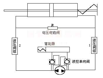
图 2 液压驱动回路原理图
机电伺服控制系统的动态特性主要取决于位置控制器和步进电机的特性。步进电机是将脉冲信号转换成机械角位移的执行元件:步进电机转子的角位移的大小及转速分别与输入的电脉冲数及其频率成正比,并在时间上与输入脉冲同步。图 3 为闭环步进位置控制系统的动态结构图,它包括位置控制器、被控对象和反馈通道等部分。
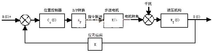
图 3 闭环步进位置控制系统的动态结构图
根据电液转换器的位置控制特点和最小拍控制理论,可得广义对象传递函数为:

式(1)广义对象传递函数
考虑到泄漏系数可以通过制造精度的提高而减少到不足以引起系统误差,因而可以忽略泄漏系数的影响,式(1)变为:
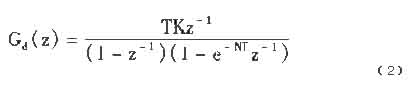
式(2)简化后的传递函数
式中:T——位置检测采样周期;K——对象增益(K = K_F·K_θ·K_P·K_YA / V_C);N =(V_C + A²·E_Y)/ V_C。
根据内啮合齿轮油泵的工作原理,油泵的流量为:
Q = dv/dt = K_P · dΦ₁/dt (3)
对式(3)进行拉氏变换,并以油泵流量为输出、以电机转角变化为输入,得:
W(s) = Q(s)/Φ(s) = K_P·s (4)
根据液流的连续性,考虑到液压缸的泄漏及油液的压缩性,并且液压阀无流量调节功能,则回路的流量方程为:

式(5)回路流量方程
对式(5)进行拉氏变换,并以流量为输入、以位移为输出,得:

式(6)回路传递函数
根据前面的理论分析和图 3 所示的系统结构,近似认为泄漏系数 K1=0,可得系统开环传递函数为:

式(7)系统开环传递函数
式中 Kd = K_F·K_θ·K_P·K 为系统增益。当 Kd = 280 时,根据式(7)作出的开环波德图如图 4 所示。
根据奈魁斯特判据,当开环传递函数在右半 S 平面没有极点时,闭环系统稳定的充分必要条件是:低于增益穿越频率 ωc 的频率范围内开环相频率特性不穿越 -180° 线,相位裕量 γ 不小于 30°~60°,增益裕量 Kd 不小于 4dB。
由图 4 可知,相位裕量 γ 为 90°,增益裕量 Kd 为 11dB,符合奈魁斯特判据,所以系统是稳定的。
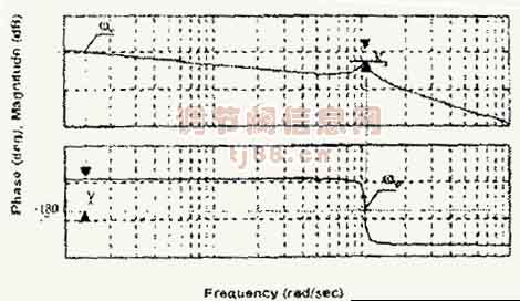
图 4 智能电液执行器控制系统开环波德图
通过对智能阀门电液执行器动态特性的分析,可以得出如下主要结论:(1)智能阀门电液执行器系统稳定、系统响应速度快,并且减少系统增益、减少液压油缸的行程和增加阻尼均可增大系统稳定裕量;(2)当不考虑智能电液执行器的泄漏系数时,系统无稳态误差,因此只要使智能阀门电液执行器的泄漏系数控制在微小值范围内,可以改善系统动态特性、减少稳态误差;(3)使用智能阀门电液执行器直接调节阀门,可以节省投资、检修和维修费用,且因其作用力大而无卡涩滞后等缺陷,使调节的安全性和可靠性得以大幅度提高。
The hydraulic circuit consists of a double-rod cylinder, valve group, bidirectional internal-gear pump, high-pressure solenoid valves and springs (Fig. 2). The bidirectional fixed-displacement internal-gear pump controls cylinder direction and speed by changing pump speed and flow direction; circuit pressure follows the load, so there is no surplus pressure or wasted flow — high efficiency. Return back-pressure acts directly on the pump inlet, becoming driving torque and reducing prime-mover power; hydraulic shock from reversing inertia is likewise recovered as pump-driving power. Direction changes via the pump produce little shock, suiting high-power, frequently reversing systems.
Fig. 2 Hydraulic drive circuit
Servo dynamics depend mainly on the position controller and the stepper motor. The stepper converts pulses into angular displacement: rotor angle and speed are proportional to pulse count and frequency, synchronised with the input pulses. Fig. 3 shows the dynamic structure of the closed-loop stepper position control: position controller, plant and feedback path.
Fig. 3 Closed-loop stepper position control structure
From the position-control characteristics of the electro-hydraulic converter and deadbeat control theory, the generalised plant transfer function is:
Eq. (1) generalised plant transfer function
Since the leakage coefficient can be reduced below significance by manufacturing precision, it may be neglected and Eq. (1) becomes:
Eq. (2) simplified transfer function
where T — position-sampling period; K — plant gain (K = K_F·K_θ·K_P·K_YA / V_C); N = (V_C + A²·E_Y)/V_C.
By the pump's working principle, its flow is:
Q = dv/dt = K_P · dΦ₁/dt (3)
Laplace-transforming Eq. (3), with pump flow as output and motor angle as input:
W(s) = Q(s)/Φ(s) = K_P·s (4)
From flow continuity, allowing for cylinder leakage and oil compressibility and noting the valve has no flow regulation, the circuit flow equation is:
Eq. (5) circuit flow equation
Laplace-transforming Eq. (5), flow in and displacement out:
Eq. (6) circuit transfer function
From the analysis above and the structure of Fig. 3, taking leakage coefficient K1 ≈ 0, the open-loop transfer function is:
Eq. (7) open-loop transfer function
where Kd = K_F·K_θ·K_P·K is the system gain. With Kd = 280 the open-loop Bode plot from Eq. (7) is Fig. 4.